
An earthquake is an unavoidable and unpredictable herbal phenomenon that frequently reasons harm to lives and belongings. We can’t combat it however we are able to live alert and aware the usage of erawhich can guard us and the industry. here a simple earthquake indicator for home and industry the use of an Arduino and a noticeably–sensitive ADXL335 (Fig. 1) accelerometer is offered which can suggestvibrations.
This mission can be changed and used as a knock-and-shake detector for ATMs, vehicles or door-wreckalarms. however its fundamental aim is to discover earthquakes and other seismic sports.
We know that accelerometers like ADXL335 are fairly sensitive to knocks and vibrations in any of the threebodily axes. ADXL335 gives analogue voltage equivalent to imposed acceleration. It has three outputs, oneevery for of X-, Y- and Z-axes. The 3 analogue outputs are wired to Arduino Uno ADC pins. Any accelerationprompted because of movement in any of the axes is detected with the aid of the accelerometer andsubsequently via Arduino ADC.
If movement is violent sufficient at some stage in an earthquake and crosses a sure threshold, a nearbyalarm light (LED) glows, a buzzer sounds in addition to a relay energises. at the same time as the buzzer and light is for domestic purpose, relay output is for commercial motive; it could be stressed out to a p.cfor safety interlocking of any transferring gadget part and furnace control for shutting those down in case of an earthquake. the threshold adjustment buttons are there for wearing out this undertaking. An lcd has been provided for viewing threshold adjustments and for making the machine person–friendly.
free films here
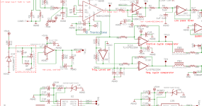
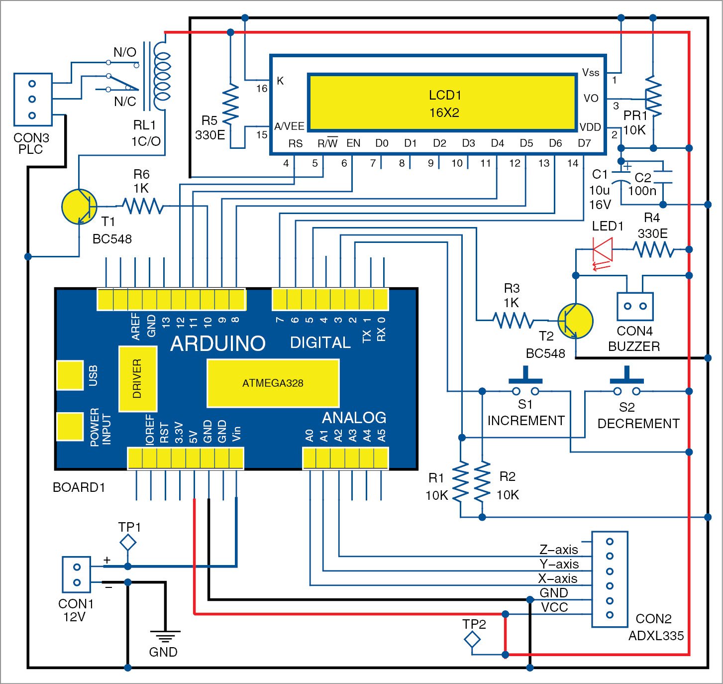
Circuit and operating
The circuit (Fig. 2) makes use of Arduino Uno board stressed to ADXL335 accelerometer module (connected throughout CON2) with its ADC inputs, namely, X-axis to A0, Y-axis to A1 and Z-axis to A2.pushbuttons via supply of 5V are stressed out to Arduino Uno interrupt pins 2 and 3 which might be pulledall the way down to floor through resistors R2 and R1. these buttons are used for incrementing and decrementing the brink of vibration detection. A sixteen×2 lcd (LCD1) is stressed out in 4–wire mode with Arduino pins assessment control and backlight enabled.
fig-2
Fig. 2: Circuit diagram of the earthquake indicator
fig-5
Fig. three: Initialising mode
fig-4
Fig. four: monitoring mode
fig-3
Fig. 5: Indicating mode
BC548 transistor (T2) is connected to pin five of Arduino for switching on the nearby alarm LED (LED1) and a buzzer connected throughout CON4. every other BC548 (T1) is connected to pin 10 for de-energising a relay (RL1) in case the alarm is induced for industrial percent interfacing for protection interlocks. Pinseleven, 12, 9, eight, 7 and six are used for lcd manipulate and facts lines. when the setup is powered, and even as it’s miles nevertheless, it reads and shops modern-day accelerometer values in Arduinoinner EEPROM irrespective of its orientation.
for the reason that ADC is 10-bit, unique header document has been provided with the code. A 5–seconddelay has been furnished for all voltages and for the system to be strong earlier than any preliminary costis read. Arduino’s microcontroller reads all three axes information from the accelerometer and shops within the EEPROM. It also stores the default threshold cost of 25 inside the EEPROM.
some traditional indicators on the liquid crystal display (Fig. 3, Fig. 4 and Fig. five) are shown right here for distinctive operating modes. In initialising mode (Fig. three), device parameters are initialised. Intracking mode (Fig. four), the gadget enters into tracking mode with modern threshold price displayed onthe second line of the liquid crystal display.
In indicating mode (Fig. 5), the gadget reads accelerometer values continuously and compares those withpreceding regular values of the accelerometer, stored in the EEPROM even as initialising. If contemporarycost differs, this is, if stored price is both more than threshold cost in advantageous facet or less than threshold value in terrible side, the alarm sounds and the relay is de-energised. This design and codinghelps nice as well as bad values in all 3 axes.
Pushbuttons linked to pins 2 and 3 of Arduino function interrupts for incrementing and decrementing threshold values for sensitivity changes. For earthquakes, a threshold of 10 to 15 is ideal. The sensor also can be used to stumble on knocks and vibrations if the edge is set to 5 to 8.
The complete setup may be wired and enclosed in a difficult enclosure and hooked up anywhere inindustry or domestic. users also can calculate resultant acceleration with the aid of the usage offormulae of rectangular root of X2+Y2+Z2, in which X, Y and Z are outputs from ADXL335, and thencompare the result with the threshold to elevate an alarm. modifications may be achieved by using theconsumer on the same platform, if required.