
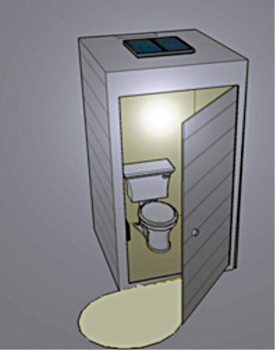
notwithstanding being more high-priced than standard everlasting outdoor bathrooms, portable toilets(Fig. 1) have several enormous advantages as these are self-contained and can be placed nearlyeverywhere. nowadays transportable toilets are frequently visible at out of doors regions likeconstruction web sites, farms, camp websites and even street–sides. sun strength offers a superanswer for packages in which lighting fixtures is needed in transportable lavatories which can bepositioned far from a mains supply grid, or the installation is predicted to be on the site for a quickduration.
here is a circuit of a self-contained sun mild for portable bathroom lighting fixtures packages. The solarlight housed inside its very own enclosure incorporates a solar charger, rechargeable battery p.c., white LED mild source and PIR movement sensor as an occupancy sensor. The occupancy sensor (movementsensor) activates the light source and, after the booth has been vacated (or when there may be no validmotion), the lighting fixtures switches off to store battery.
Circuit and working
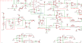
Circuit diagram of the solar light for a transportable toilet is proven in Fig. 2. it’s far constructed arounda 9V, 450mA sun panel, voltage regulator LM317 (IC1), a PIR sensor, MOSFET BS170 (T1), a 1W white LED (LED1) and a few other components.
Fig-2
Fig. 2: Circuit diagram of the sun mild for a transportable bathroom
loose motion pictures here
The circuit can be cut up into two sections: the charger and the sensing and manage gadget. energy isfurnished through the 9V, 450mA-rated polycrystalline solar panel, which is linked to CON1 and fees the4.8V, 1800mAh battery %, BATT.1, thru the regular–current charger constructed round IC1. The 6.8-ohm resistor (R1) limits the charging current to near one-tenth fee of the battery, this is, 180mA.
elements list
The sensing and manipulate circuitry is based on PIR movement detector module (Fig. three), which isconnected across CON2. whilst a legitimate movement is detected, output of the PIR sensor is going toround three.3V and the light source LED1 (3.6V, 1W white LED) is switched on thru medium-electricityMOSFET BS170 for a finite time. The four.7-ohm, 1W resistor R2 limits the running modern-day of the white LED.
Fig-3
Fig. 3: photo of the PIR sensor
creation and testing
An actual–length, unmarried–facet PCB for the sun mild for a portable lavatory is shown in Fig. 4 and itsfactor layout in Fig. five. Enclose the PCB in a suitable small box in the sort of way that it can beoutfitted in the toilet.
Fig-four
Fig. four: real–length PCB of the sun light for a portable rest room
Fig-5
Fig. five: factor layout of the PCB
download PCB and element layout PDFs: click on here
After assembling the PCB board, connect the absolutely-charged battery % BATT.1 to the circuit and turn on S1. The PIR movement sensor detector calls for an initialisation time of approximately 60 seconds (or maybe up to a few mins). Thereafter, it enters standby mode, ready for detection.
you can modify the postpone potmeter in PIR sensor clockwise to growth the time put off from threeseconds to as much as 300 seconds. similarly, turning the sensitivity pot in PIR sensor clockwise increasesthe detection sensitivity from three to 6 metres. In a few PIR sensor potmeters, the LDR socket choice isn’tprovided.
The sun panel (no longer equipped within the enclosure) can be hooked up at the perfect vicinity. Battery percent BATT.1 is fine connected to the circuit through two flexible, well-insulated multi-strand wires. Then, a warmness-sink ought to be introduced to IC LM317.
ultimately, house the assembled PCB in a small plastic case with holes drilled for the connectors for linking the sun panel, transfer S1, LED1 and PIR movement sensor. The suggested enclosure is proven in Fig. 6.
Fig-6
Fig. 6: advised enclosure
EFY note. join LED1 externally, with a proper warmness-sink, to CON3 inside the PCB.