solar streetlights can be without problems integrated with a nightfall–sunrise controller by truelyemploying a pnp transistor and a few resistors in which the solar panel itself works as the sensor. but whatapproximately different lights assets that don’t rent solar panels together with automated lightsstructures in small wind generators, automatic lighting fixtures in automobiles or battery based totallystructures in which automatic lights is essential?
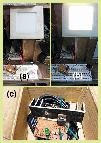
A simple, low-price, yet an effective answer for the nightfall–dawn controller circuit is described here.author’s prototype is proven in Fig. 1.
Circuit and operating
Circuit diagram of the nightfall–sunrise controller is proven in Fig. 2. it’s far constructed round a mild–dependent resistor (LDR1), n-channel MOSFET IRF640 (T1), 12V LED mild or a small inverter (100W) andsome other additives.
unfastened films here
The 12V battery-operated circuit is designed such that the common battery deliver is used for running the circuit as well as for load, this is, for electricity LED/small inverter circuit. Resistors R1 and R2 are used as a voltage divider and a modern limiter inside the circuit, respectively. LED1 is used as circuit de-activation indicator. LDR1 is the primary aspect for actuation of the nightfall-to-sunrise sensing. The n-channel MOSFET IRF640 is for the switching motion of the LED light or the small inverter connected to the gadgetthrough switches S1 and S2, respectively.
elements listWith sunlight hours falling on LDR1 (dawn mode), resistance of LDR1 turns into low, a smallcutting-edge flows via LED1 and it glows. at the identical time, because of low voltage throughout LDR1, MOSFET IRF640 does now not trigger. So load (LED light/inverter) remains off.
however whilst the encompassing area of LDR1 (nightfall mode) is dark (at night), resistance of LDR1turns into very excessive, no contemporary flows thru LED1 and it does now not glow. at the same time,due to better voltage throughout LDR1, IRF640 triggers. So load mild (power LED light/ inverter) comes on, provided transfer S1 or S2 is on.
IRF640 can take care of a maximum modern of about 18A, however you can limit its application toabout 8A-9A only, based totally on which the warmth-sink is hooked up to the MOSFET.
Fig-2
Fig. 2: Circuit diagram of the nightfall–sunrise controller
construction and checking out
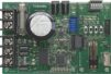
An real–size, unmarried–facet PCB for the nightfall–sunrise controller is shown in Fig. 3 and its thingformat in Fig. four.
Fig-three
Fig. 3: actual–size PCB sample of the nightfall–dawn controller
Fig-4
Fig. four: issue layout of the PCB
down load PCB and component format PDFs: click on right here
After assembling the circuit, enclose it in a suitable field. The unit need to be fixed at the pillar in one of these way that the daylight hours falls directly on LDR1.
Bikash Rai is assistant engineer in energy & energy department, authorities of Sikkim. He is also a part-time studies scholar at Sikkim Manipal Institute of era, Sikkim